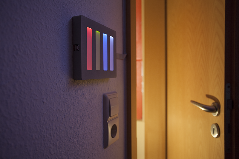
This control unit is made for this Lamp and offers a simple way to interact with it.
The control unit has three main purposes. It obviously contains a microcontroller which controls the lamp itself. With the built-in touchscreen one can interact with the lamp, for example set the brightness of different colors. The third purpose is to be a gateway between a computer and the lamp, this way I can realize the music visualization.
Hardware
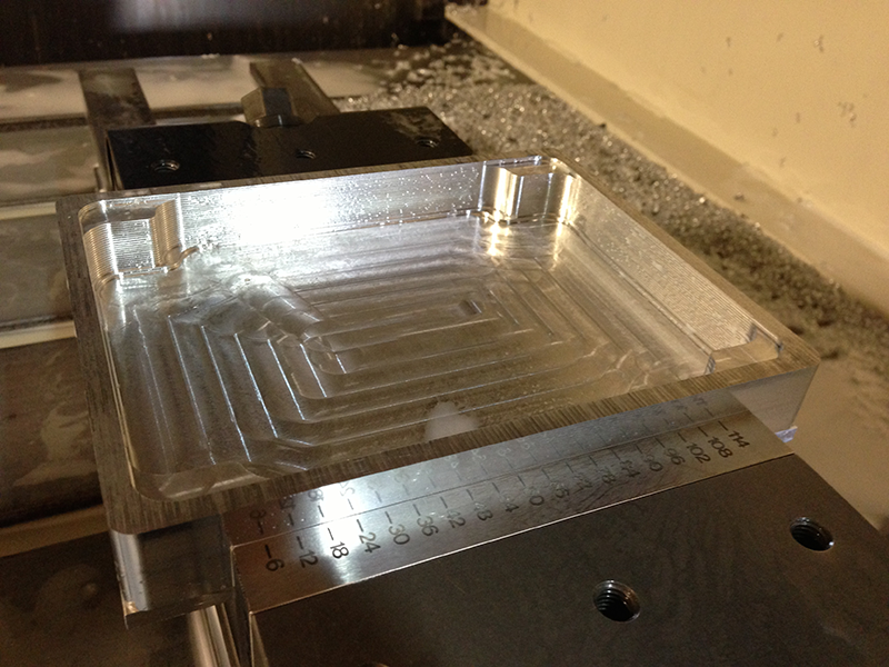
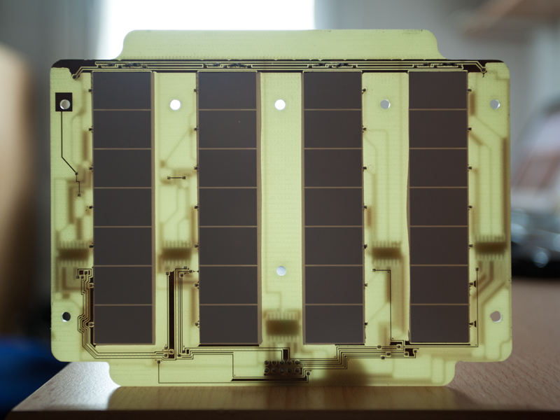
The enclosure is essentially one aluminum part, I think it qualifies to be called unibody design. This picture shows the unfinished part on the milling machine. It got an anodized finish after the milling process. There are four touchscreen sliders in the front to manipulate the brightness of the individual colors. This self-made capacitive touchscreen went through several iterations. The hardest part was to get the finger as close as possible to the sensing pads on the PCB. This was difficult because I also wanted a backlight and that needs to be in front of the sensing pads to be visible. So there are actually multiple layers in front of the PCB.
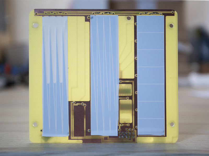
The first layer is the one which is touched, it's a 1mm thick Polycarbonate sheet. The backside is sand-blasted so the light is a bit more diffused. Located after that is the part which is responsible for the spreading of the backlight. It's originally from a real edge-lit display. This special diffusion panel spreads the light from the LEDs evenly over the area of the touchscreen. The SMD LEDs are positioned at the top edge and soldered to the PCB in an upright position. This way they emit the light into the side of the diffusion panel. Now one could still see the sensing pads so a white tape is placed over them, with the nice additional effect that the light is reflected better. Then there is the touchscreen PCB, it holds all these layers by pushing them together.
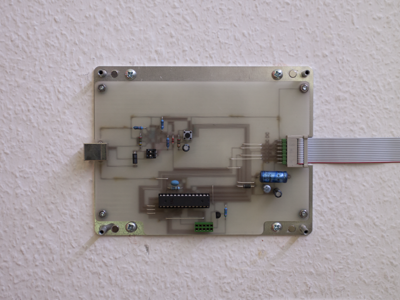
Only having this aluminum enclosure isn't enough, clearly there needs to be some kind of mounting. An aluminum sheet serves as wall mount and is screwed to the wall. The wall mount has pressed in so called self-clinching standoffs, they serve as guidance, so the enclosure can slide right on the wall mount. There are additional magnets to keep the enclosure on the wall mount. The mainboard PCB with the microcontroller is also attached to the wall mount. Simple pin headers and sockets are used to connect the mainboard with the touchscreen PCB.
Electronics
The mainboard is basically a self-made Arduino Uno. The whole development was made with an Arduino so I decided that the finished product should also have one, that way I'm easily able to modify the software again. I wanted the control unit to be as thin as possible, therefore it would be a waste of space and development board to just build in an Arduino. Consequently I studied the Arduino schematic and replicated the relevant parts for my project. Instead of the Atmega16U2 microcontroller for the serial communication I used an FT232R.
All Arduinos have bootloaders so they can easily be programmed by the Arduino software. There is no bootloader on a freshly bought Atmega328, but to use the microcontroller with the Arduino software the bootloader is needed. It's really easy if there are two Arduino Unos lying around, one microcontroller is swapped with the new one and the other Arduino is used as programmer to burn the bootloader. This tutorial explains this in detail.
I wanted a capacitive touchscreen and I wanted to build it myself. First thing was to do some research on capacity sensing with an Arduino and this tutorial pops up really fast. There are two pins needed for this method, between them there is a resistor and a capacitance (the human finger). When one pin changes its state the capacitor slowly loads and at some point the other pin receives that changed state. The longer the time between sending and receiving is, the greater is the capacitance. With that time value one can tell whether or not a human finger is near the sensing pad. I tried that, it worked and it's probably alright for a simple project, but my touchscreen has some special requirements so I didn't get a prototype to work satisfyingly. This method is rather slow, it needs two pins and the measuring time is not fixed because it depends on the capacitance. As I explained in the hardware section there are several millimeters between the sensing pads and where the human finger touches. To get a higher sensitivity to sense through all those layers the resistance can be increased. But now the measuring time also increases because it takes longer for the capacitor to load. This is critical because I need at least 8, probably even 28 sensing pads.
I thought of two ways to build that slider touchscreen, one being with multiple single pads and the other with an analogue pad where the pad area decreases. The single pad version is kind of digital, I know when one pad gets "activated" the finger must be there. The analogue version is a bit more trickier because the sensed value depends on the finger position on the pad. Smaller values mean that the finger is positioned where the pad has less area. While trying out my prototypes I realized that the analogue version wouldn't work without a lot of additional work. With the distance and materials between sensing pad and finger it's not possible to achieve the required precision.
After some more research I found another, more elegant, way to measure the capacitance. This method is faster, has no variance in measuring time and only requires one analogue input pin. It's using a lot of the already built-in functions of a microcontroller. The internal sample and hold capacitor (used to stabilize analogue measurement) is essentially connected to the external capacitor, the human finger; both have different charges. The resulting charge, after connecting the capacitors, tells the microcontroller the actual capacitance of the external capacitor. That's only a brief and improper explanation, check out this post, the method is explained in detail there.
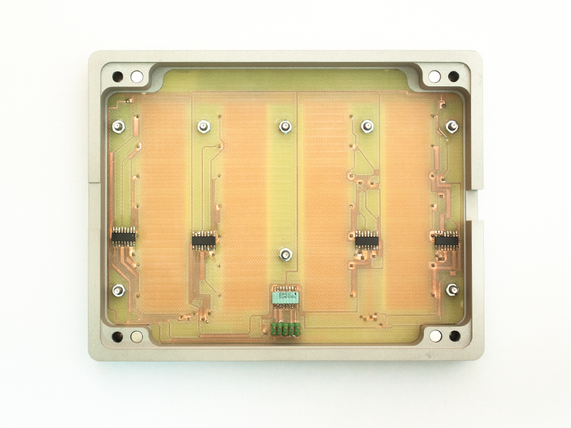
The finished version of the touchscreen uses this measuring method and single pads. But I can't just connect every pad to an analogue input of the microcontroller. There are 4 * 7 pads but only 6 analogue inputs. This is solved by using an analogue multiplexer, the 4051. Now I only need one analogue input for one slider. Multiplexing also comes with a downside: the chip introduces new capacitances so the measurements get less precise. But it's still good enough to sense fingers as shown in the video. But if I ever build another touchscreen I'll probably test different analogue multiplexer first.
Software
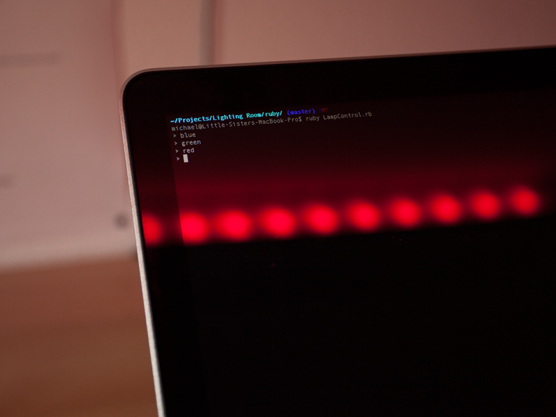
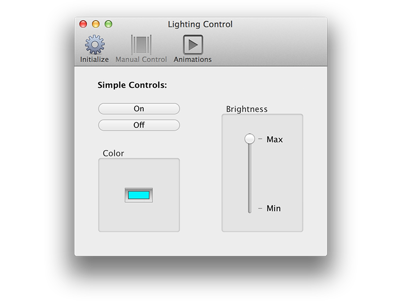
As I described in the lamp post I'm using the TLC5940 LED driver. There is an Arduino library for that LED driver available. The touchscreen code is inspired by the post I already referred to earlier. To communicate with the computer I needed some kind of protocol, that protocol is based on this tutorial. As indicated and shown in the video I can also control the lamp with a computer. First I built a little ruby script to send commands from the Terminal. After that I built a GUI from where I can easily control the color and the brightness and also do some music visualization. The App is made with Xcode and MacRuby (is currently not running on Mavericks or later) and the data for the music visualization comes from Quartz Composer.