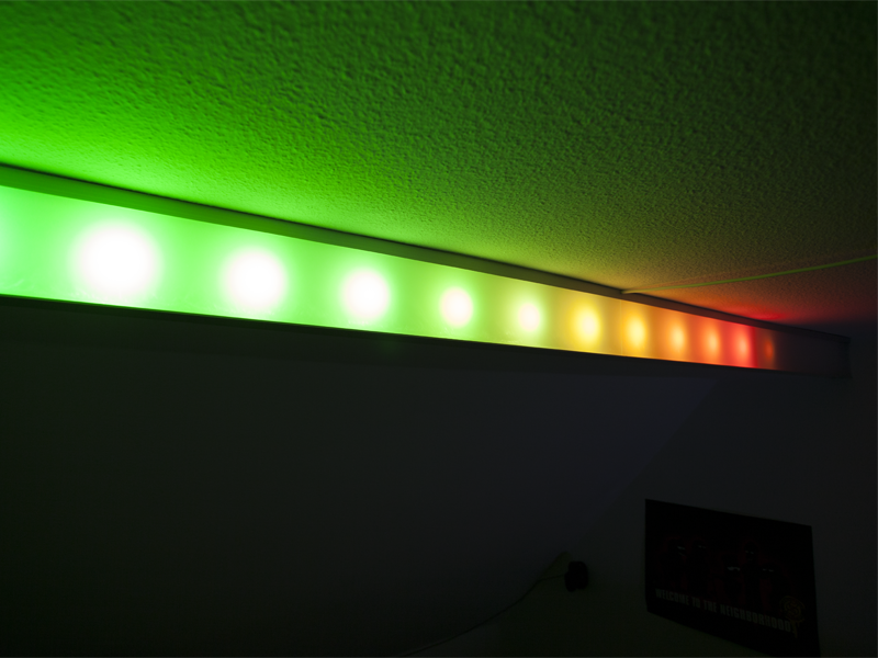
This power-saving yet awesome RGB LED lighting was only in my head for a long time - and is now finally at my room's ceiling.
The LED Lighting project is divided into two posts, here the link to the Control Unit post.
Hardware
This lamp is made to fit exactly into the destined room. Like the room, the lamp is also about 3 meters long and mounted on a ledge on the ceiling. The whole construction consists of 4 main parts, the U- and L-profile, the bottom plate and the Plexiglas in the front. The visible aluminum parts (U-Profile and bottom plate) are, for a finer look, anodized. Because the house is kind of old, the walls and ceiling aren't perfectly straight. Which means I have to compensate mechanically for the slanted walls. And this needs to happen in every possible direction. The L-profile is pushed from the wall at the bottom with a bolt. This bolt in combination with a thread in the L-profile helps to adjust the distance. To compensate the height differences between the left and right side, I used the U-profile to hide where the Plexiglas ends. While designing the lamp I intended to have no visible bolts or screws, so it just integrates seamlessly into the room with no obvious means of attachment. This is done by connecting the bottom plate to the L-profile with bolts which are not visible from the outside. And the L-profile is screwed to the wall. The U-profile is obviously mounted on the ceiling, so there are no visible screws, but the Plexiglas needs to be fastened there somehow. It's basically standing in a notch in the bottom plate and leaning against the U-profile. There are magnets mounted on the Plexiglas and inside the U-profile in such a way that they repel each other, now I can be sure that the Plexiglas always leans toward the front.
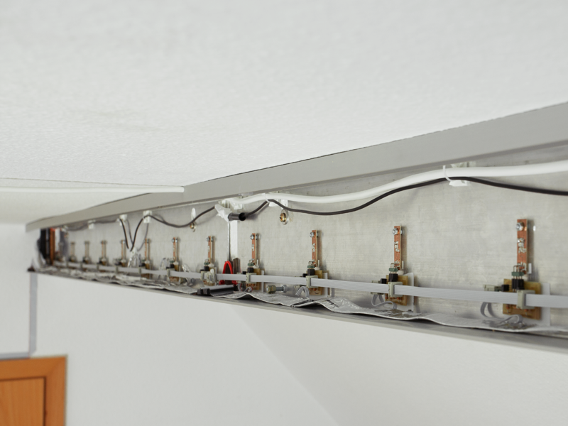
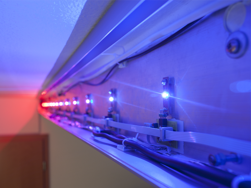
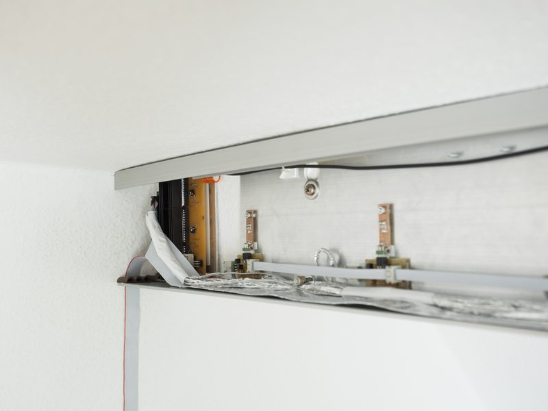
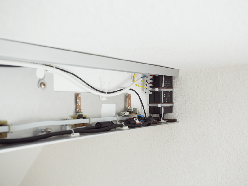
The obsolete old lamp in this room now serves as power source for the new one. The power cable goes directly from the old to the new lamp and into the switching power supply on the right side. Then there are the evenly distributed 16 RGB LEDs. And all the way on the other side there is the PCB with the electronics for the LEDs.
Electronics
I chose the enclosure to distribute the 5 V because the LED driver (TLC5940) is a constant-current sink driver, so the cathode of the LED needs to be connected to the driver and the anode to 5 V, which is the enclosure. Besides the 5 V connection from the power supply to the enclosure there is a cable for the GND connection to the PCB on the left side. There are three TLC5940 on the PCB itself, with each I can control 16 individual LEDs, so every single RGB LED is adjustable. The control unit, which sends the commands to the drivers, is covered in this post.
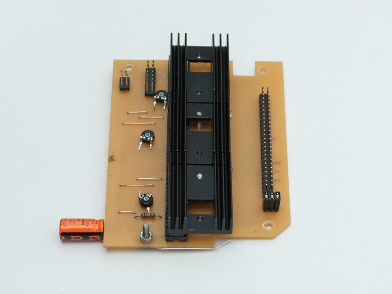
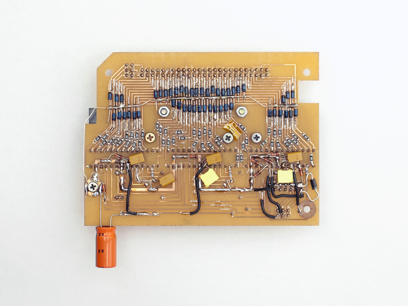
After playing a bit on the breadboard and moving on to the real thing, almost everything failed. The LEDs are connected to the PCB with ribbon cable because it is easy to split up. Accordingly all the power for the LEDs is transferred over several meters of that ribbon cable. This becomes a problem because the LED driver uses PWM (explained in the LED Cube post) to adjust the brightness of the LEDs. The LED driver rapidly turns a channel off, this can lead to voltages as high as 50 V in the ribbon cable due to electromagnetic induction, which can easily damage the LED driver. To solve this problem I used Zener diodes, which basically cut off everything above the specified Zener voltage (7.5 V). The PCB looks a bit messed up because these were all additional changes. The inductance in the ribbon cables also makes it harder for the LED driver to control the current for the LEDs.
At this point the lamp was working somehow but I thought it could be a bit brighter, the power supply and the LEDs still have some capacity left. And then there is a lot of noise in the logic circuit from the high power PWM signals. To improve this situation every LED got another little PCB. This basically outsources the power part from the LED driver to this little circuit. The advantages are that the LED driver isn't getting hot and I'm not limited by its output current rating anymore. The PNP transistors on the little PCBs now convert the signal from the LED driver to a power signal for the LEDs. Additionally I split the GND into a power path for the LEDs and a path for the logic circuit, that improved the voltage stability a bit.
A goal of this project was to replace the old lamp with the light bulbs, however there is one issue the LEDs solve less satisfyingly, and that's light quality. The light bulbs cover the whole light spectrum more or less evenly, with a peak in the red tones. When the RGB LEDs add up to create white light, the human eye sees white light but in fact there are three peaks in the light spectrum. The parts in between the peaks are missing, this means for example that pictures won't look the same compared to other light sources. What you want to do when using LEDs as lighting is add a fourth white LED, which covers the light spectrum more evenly. Concerning power, the old light bulb lamp used 120 W to illuminate this room, the LED lamp uses a maximum 30 W, which is only a quarter. But it could be even more efficient, as I'm still wasting a lot of power with the series resistors for the LEDs. This could be improved by using some sort of DC/DC converter.
Lessons learned
- Old houses may not have straight walls
- Electromagnetic induction can produce voltages dangerous to the circuit
- The quality of white light made by RGB LEDs isn't perfect