After thinking it would be a great idea to have a 3D-Printer, I fulfilled my wish to play with one in the end of 2011.
For the people wondering how 3D-Printing works, I'll explain it briefly. You take a 3D model, which you have made yourself with a CAD program, downloaded from the net or got somewhere else. This 3D model will be processed by a program called 'slicer', it slices the model into layers and outputs them as code which a 3D-Printer can read. Driven by the code the 3D-Printer prints each layer, one after another. This kind of 3D-Printer slightly melts plastic which comes out of a nozzle and forms the 3D model.
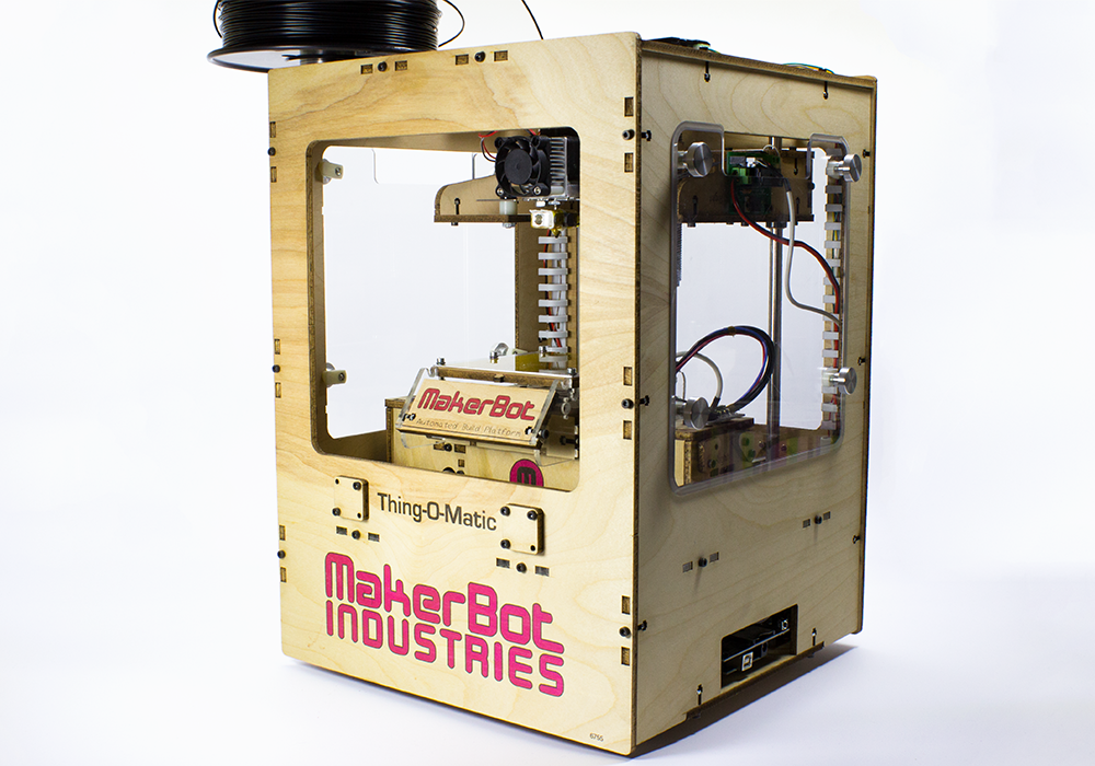
I ordered the Makerbot model "Thing-O-Matic", TOM for short. It's the last model with a laser cut wooden enclosure. My first print was a little companion cube. I was a bit surprised by the number of different parameters one can change in this user unfriendly interface from RaplicatorG and Skeinforge. For a long time I wasn't satisfied by the results, so I read and learned a lot about the topic.
Hardware improvements
A problem which persisted right from the beginning was the bending of the printed objects while printing. This happens because the plastic starts to cool and gets smaller. I started printing with "ABS", which has a worse coefficient of thermal expansion in contrast to the other popular 3D-Printing plastic "PLA". To be able to improve the ABS prints I did the following things:
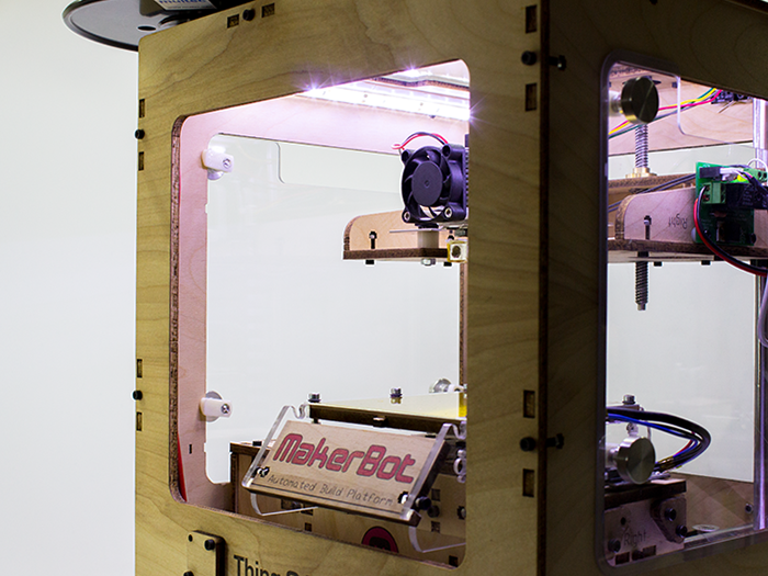
Windows
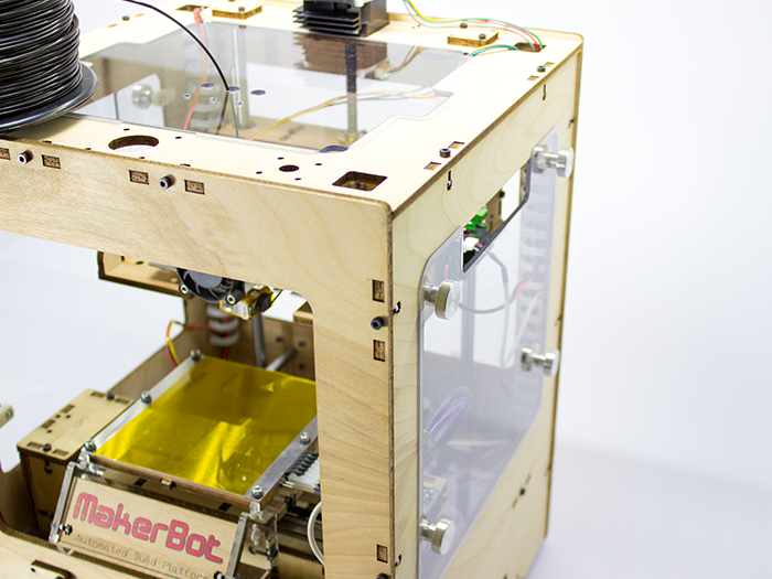
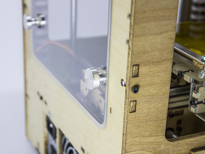
The TOM enclosure is very open, there is only material in the corners. This means the generated heat can escape rather quickly. That's why I built windows and inserted them into the frame, so the heat stays inside and the ABS doesn't cool so rapidly. Also note the top window, it's probably the most important because presumably a lot of heat exits there. But there is a reason why the enclosure is that open, it's for easily accessing all kind of different parts of the 3D-Printer. Therefore a requirement was the ability to easily remove the windows. This is done with self-made bolts which can be turned by hand. On the other side of the bolt there is a printed part with a sloped area. When the bolt is turned, it pulls the window into the frame and holds it there.
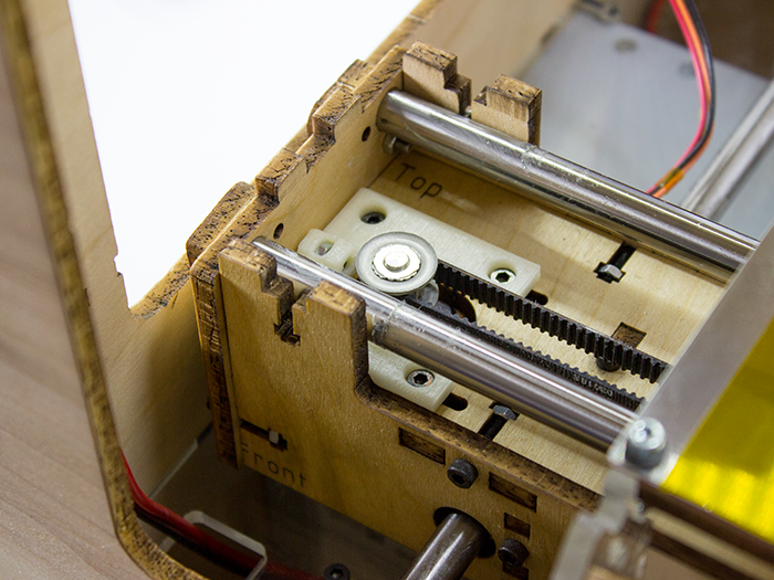
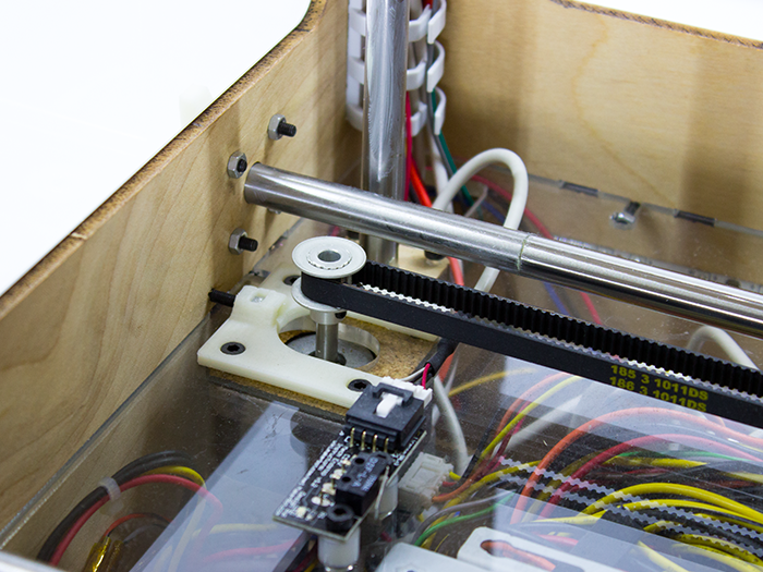
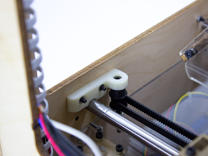
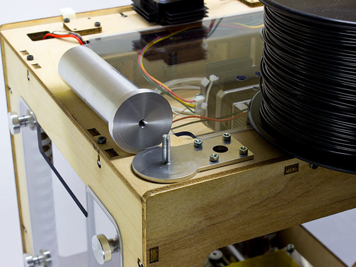
Belt tensioner
It's important that the tension of the belt is neither too tight nor too loose, otherwise the quality and dimensions of the prints suffer. The bolts which mount the motor can loosen with time, especially with all the vibration. To prevent that and easily adjust the tension, I printed this belt tensioner for my X and Y axis. And to support the other side of the Y-axis I printed this bracket.
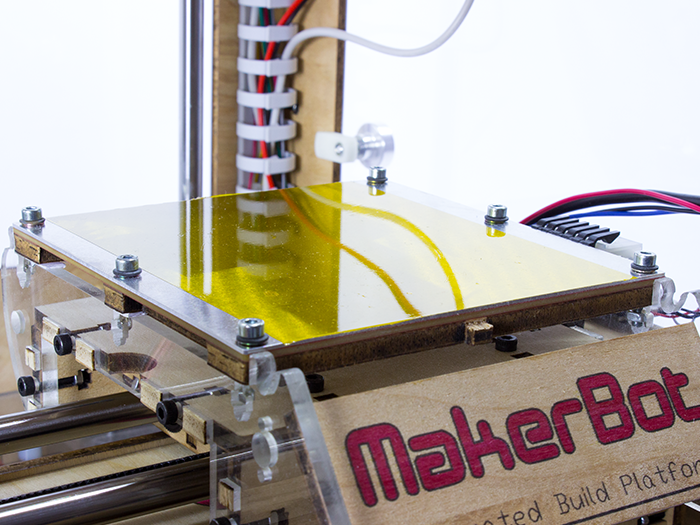
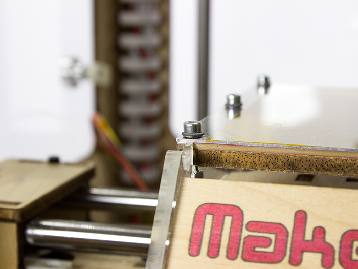
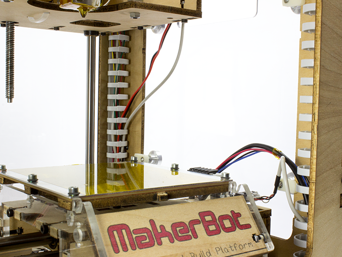
Build platform
The Makerbot shipped with an Automated Build Platform. It sounds really interesting, promising that you'll be able to just print one part after another without manually removing the last one. With a conveyor belt wrapped around the heater board the finished part moves to the front and eventually falls from the platform and the next print can begin. But this has some serious downsides so I removed the conveyor belt after a while. The belt is obviously not fixed, only tensioned to the platform. This means that, while printing, the part, still fully connected to the belt, can lean a bit when the nozzle pulls at the plastic. For a good print the object needs to be steady. The belt was replaced by Kapton tape, the printed plastic really sticks to it, especially if it's cleaned with acetone. Now I sometimes have the problem that the finished printed part sticks so well that I can barely remove it from the platform. A problem I should probably be glad about. To further improve the build platform I installed a 1mm aluminum sheet on top of the heater board because the bottom side of the printed parts visibly took on the texture of the heater board. Now the platform is even but it takes longer to heat it up.
Miscellaneous
To have a nice view of the current build and the electronics, I installed LEDs at the top and bottom. An unused 12V connector from the power supply unit was used to power the LEDs. The top ones can be switched on and off.
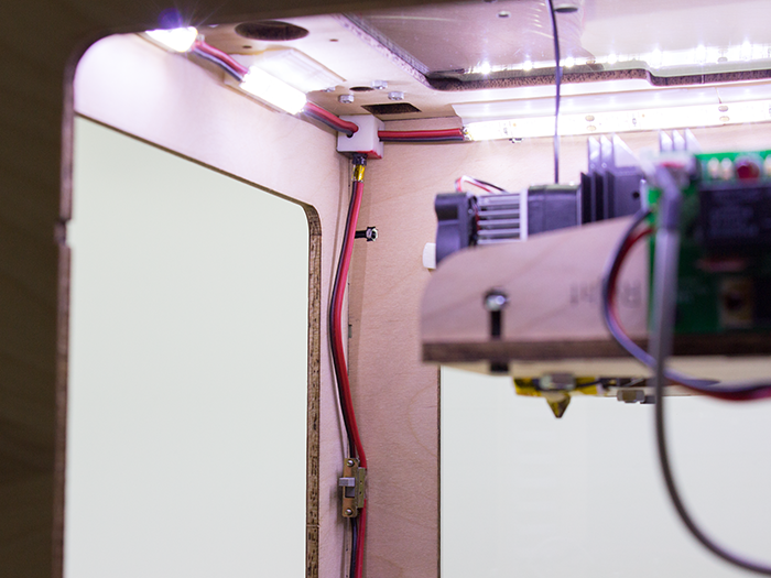
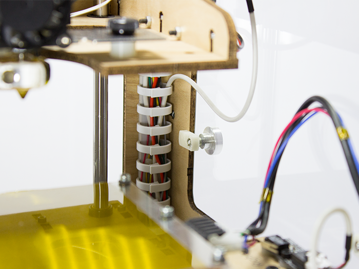
The cables inside the Makerbot needed some tidying up, this was achieved with cable guides in the corners. I also installed spool holder on top for the filament spools. They're made of two parts, if another spool has a different hub diameter I can just replace the upper part. It's also an advantage to easily disassemble the holder when the Makerbot needs to be transported.
Software
At first I used RaplicatorG with Skeinforge as slicer, there was not really an alternative. Skeinforge has a lot of parameters to adjust the print and the crappy UI didn't make it simpler. As I wrote earlier I wasn't satisfied with the print results. In search of improving the print I read about most of these Skeinforge parameters and got a good understanding about 3D Printing itself. For a good print it's really important that the first layer has exactly the right height. In the beginning the first several layers were always squashed, although I calibrated the z-height. It turned out that the threaded rod of the Z-axis has backlash. This means after the Z-stage moves down to the platform, it doesn't move up again until the backlash is compensated. It could even happen that the nozzle stays on the first layer and only moves up after two more layers are finished. I fixed this in the so called Start G-code. It's the code that is automatically added to the beginning of the G-code file. After the homing process the extruder now moves in front of the platform and 1mm deeper than the platform. By moving the 1mm up again to the first layer the backlash is compensated.
; ** Start G-code **
G90 ; Use absolute coordinates
G21 ; Set units to millimeters
M103 ; Make sure extruder is off
; Homing
G162 Z F1000 ; Home Z axis
G92 Z5 ; Set Z to 5
G1 Z0.0 ; Move Z 5mm down
G162 Z F150 ; Home Z axis
G161 X Y F2500 ; Home X Y axes
M132 X Y Z A B ; Recall stored home offsets for axis
; End Homing
G1 X25.0 Y-67.0 Z10.0 F3300.0 ; Move to waiting position
M6 T0 ; Wait for toolhead parts, nozzle, HBP, etc., to reach temperature
; Compensate Z-axis backlash
G0 Z-1
G0 Z0.2 ; First layer height
; ** Start G-code end **
After several months of living with Skeinforge I discovered the software Slic3r. Not only is it a lot simpler to use, but it's also a good deal faster than Skeinforge. Slic3r uses, like all modern systems nowadays, another dimension for the extruder, it's called "E" in the G-code but some software (like Makerware) call it "A" and "B", to distinguish between several extruders. This extra dimension didn't work with the originally shipped firmware of the Makerbot. The Sailfish firmware solves that problem and has some nice print quality improving features. Some time ago the software Makerware from the Makerbot guys added support for the TOM so I tried that, too. As silly as it sounds, I wasn't able to convince the software to turn the fan for the extruder on. There are different commands for "turning the fan on" and sadly the Makerware verification doesn't consider the one I need for my TOM as valid. It might be fixed in the future but for the time being I'm using my current setup: Slic3r as slicer and ReplicatorG for sending the G-code.
Music
Very recently I found out that the sounds from the stepper motors can be used to make music. Have fun.
To see things I actually printed visit my Thingiverse page.