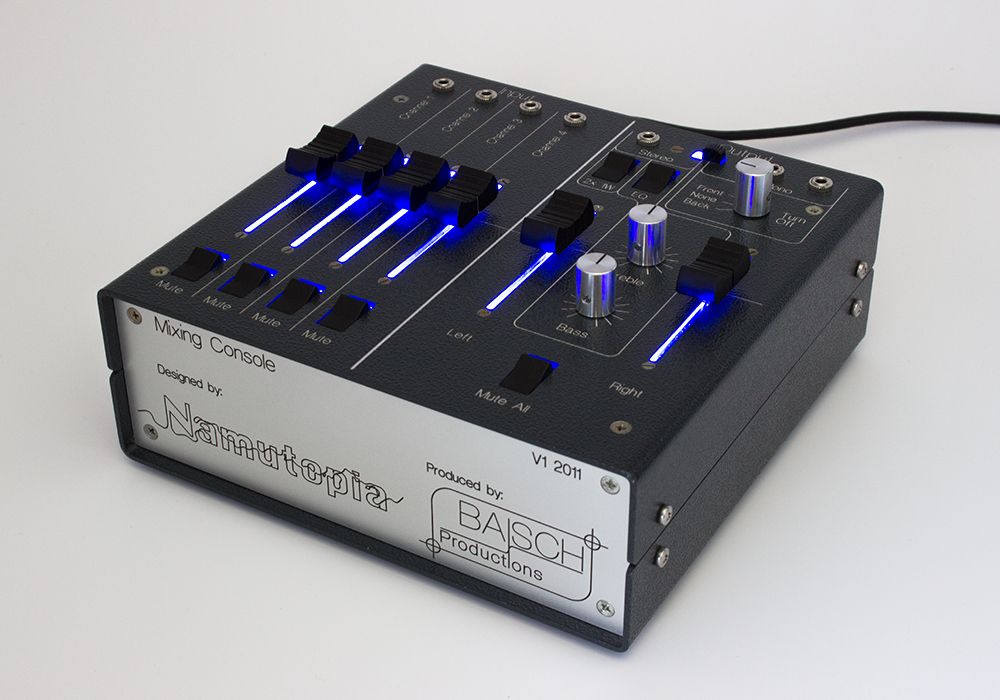
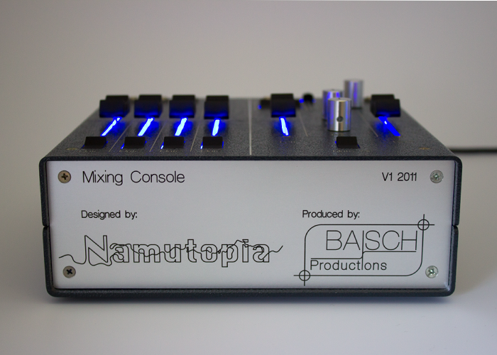
Having several Computers and only one sound system got really annoying. Every time I needed real sound on a particular computer, it wasn't connected to the sound system for sure. So I decided to build a mixing console.
The problem was that there was no mixing console with 3.5mm phone connectors. For the simple task of connecting several computers, iPads or iPhones there was just no nice solution which didn't include adapters or something else. In the beginning I thought "why not connect all of the audio sources and feed it to a speaker?". This does work if only one audio input is active at the same time. If there were two audio signals, say while fading a song, the result wouldn't sound quite nice. This is because directly connecting two voltage sources results in something like the average value of those and not the added up value you want to have. An operational amplifier makes that possible. There are a lot of use cases for op-amps and one is to add up voltage values. But now it was clear a real circuit was needed so why not build some kind of enclosure around it and then why not use those awesome faders and then why not build in a equalizer... So I ended up with a slightly more complicated mixing console than I thought at the beginning.
Audio circuit
As one possible power supply I wanted to use USB. Now an audio signal contains positive and negative voltage values. So how does one amplify an audio signal with 5V USB voltage? By lifting up the audio signal Ground from 0V to 2.5V. This is done with a capacitor and voltage divider. After that an op-amp is used to amplify the signal. The op-amp is one which is driven by 0-5V and not negative and positive voltage so I can directly use the 5V USB supply. The amplification can be controlled with the resistor [R5] which is one of the faders on the input side. Note that the op-amp is amplifying around the 2.5V reference voltage (non-inverting input) and also that the signal is inverted. After that there is another inverting op-amp which also acts as an amplifier through the resistor [R7] and additionally sums up all the signals from the 4 inputs. The capacitor [C2] only lets AC voltage pass. The initial thought for the mute function was to just disconnect the signal with a switch but that would have made the circuit design more complicated and would have meant some long traces which aren't desired. Instead I did something else stupid. The thought was to pull the signal down to Ground with a transistor. The first mistake was to pull to Ground instead, the signal should have been pulled to the 2.5V reference voltage. But that still wouldn't be perfect because UCE over the transistor is never 0V, so the voltage the op-amp would have seen on its inverting input would still be smaller than on its non-inverting input thus still amplifying this voltage difference.
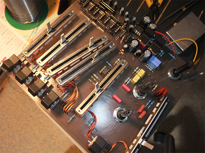
The PCB for the audio circuit is almost as big as the whole mixing console. Most of the parts which can be seen from the top like switches are attached to the PCB. I used the program Osmond PCB for layouting the PCB.
Power circuit
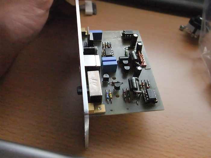
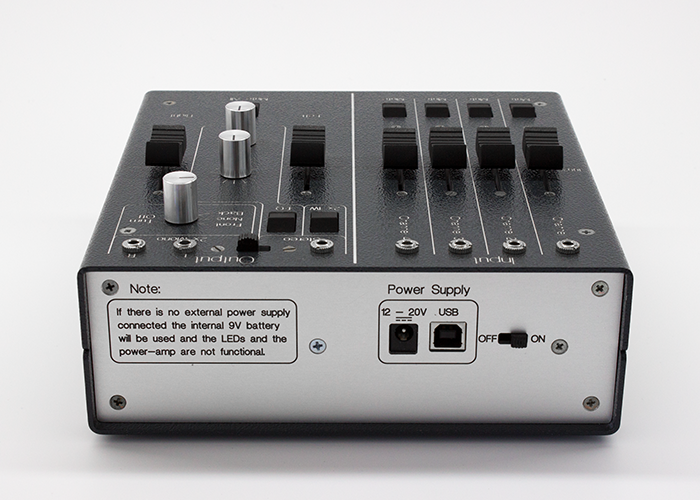
This was an extra circuit attached to the back side of the mixing console. The circuit had two main purposes. The first was to free the supply voltage from any ripples and noises, the idea was to cut something off so the noisy stuff would be gone. I used voltage regulators (TPS7301) for that but the effect wasn't as desired. I still hear my graphics card consuming power through the USB output or a keyboard with PWM backlight when it's connected to the same USB hub. It's possible that this noise is on ground potential for which I didn't build in any countermeasures. The other purpose of the circuit was to manage which power supply of the connected should be used. A little transistor circuit assigned for that task didn't perform as wanted due to two misunderstandings on my side. First, when simulating an open connection (e.g. when the USB supply isn't plugged in) don't just set the voltage to 0V instead really open the connection to the voltage source. Second, a diode does prevent current from flowing through one direction but that doesn't mean that the voltage doesn't adjust on the other side of the diode, so for logic circuits a diode isn't suitable for only letting a signal through in one direction.
Other stuff
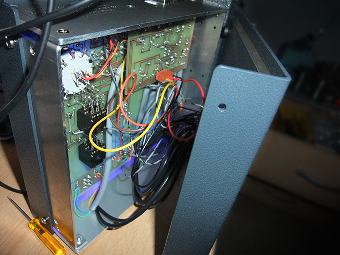
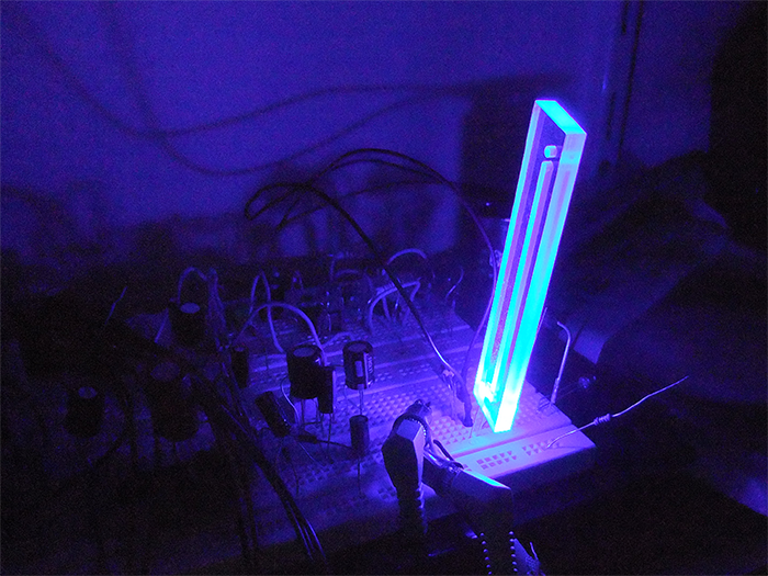
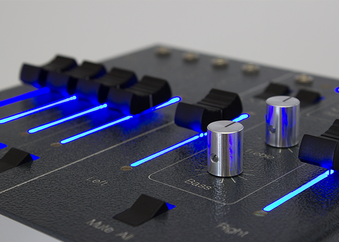
For grounding there is another small PCB at the bottom of the mixing console which also had a conducting connection to the chassis to shield everything inside. Where Ground was needed a connection to this PCB was directly made with a cable. Combining all Ground connections at one point is called star grounding and is important to prevent humming in audio circuits. The blue backlight, which looks really awesome, is just a transparent plastic behind the faders with an LED on one side. The chassis consists of powder-coated aluminum. I milled through the powder-coat to make the silver aluminum visible and therefore the layout. The front and back panel are consisting of anodized aluminum. After the milling process, one can see in the video, the groove is filled with black paint.
Lessons learned
- Pulling the signal to ground is a bad idea for this mute function.
- Smoothing the supply voltage is important and needs improvement.
- When simulating an open connection, disconnect the source instead of only setting it to 0V.
- Voltage can adjust through a diode in blocking direction.
There is a lot to improve and I hope I find the time to build a version 2 sometime soon.