It's a small quadcopter based on this Instructable project called “Picopter”. In 2013 this Instructable inspired me to build my own little copter. The original Picopter project is really nice, but I had some additional hardware, electronics and software ideas to make it an interesting challenge for me. In 2020 I finally had some time to finish and document the project.
Hardware
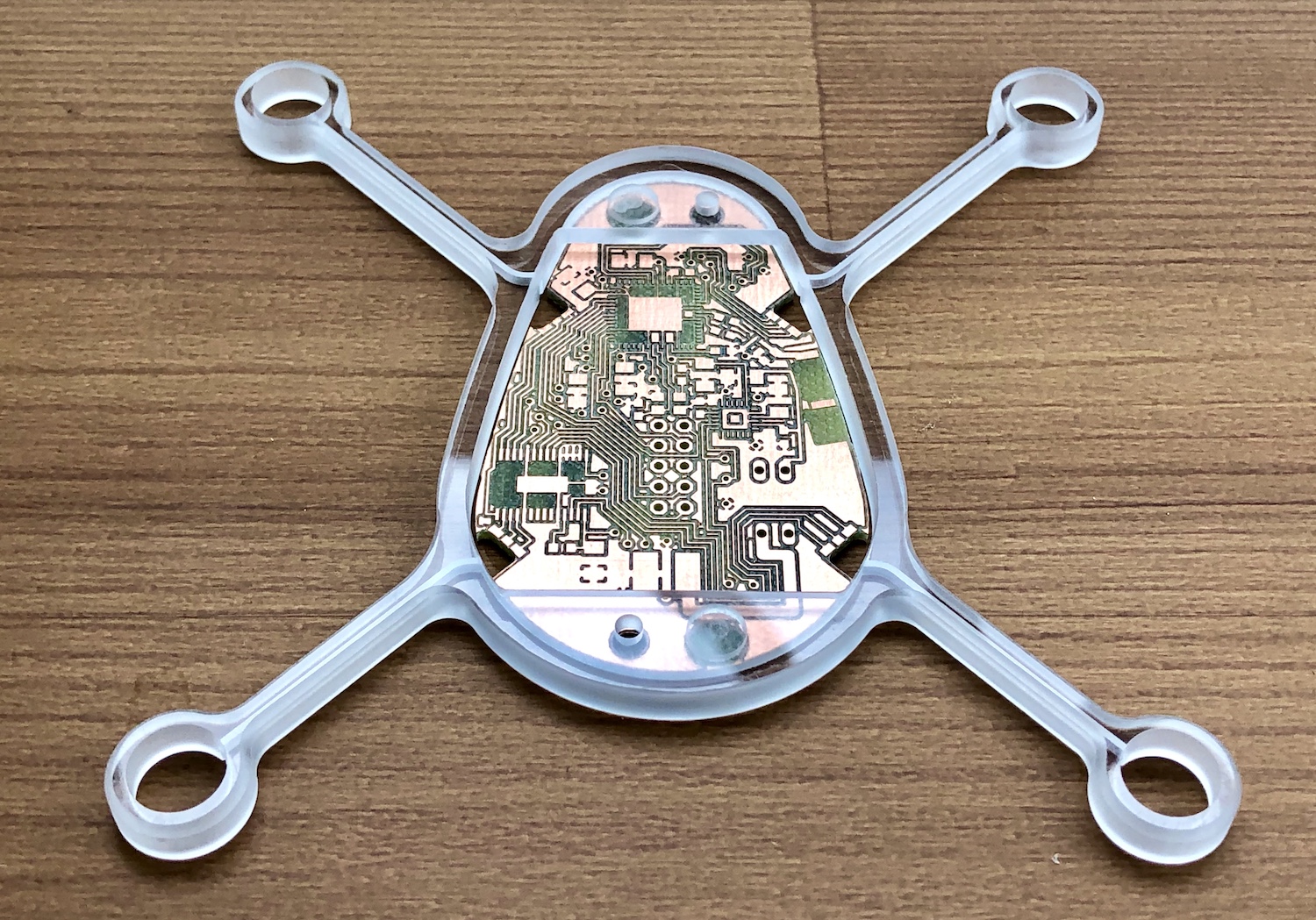
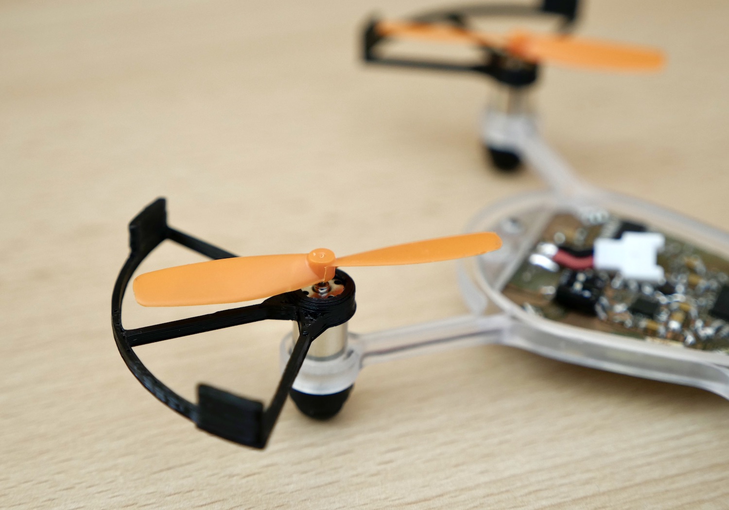
I had the feeling that this little flying copter seems almost lively, and that it deserves a more organic look. A look that now consists of a mixture of transparent milled polycarbonate and black 3D printed ABS. This allows for light effects, organic shapes and at the same time shows the aesthetics of electronics. This new shape gives the copter a clear direction, which is important during flight. The frame now holds the motors by a fit. The motors came with a rubber cap that are now used as landing legs for the copter.
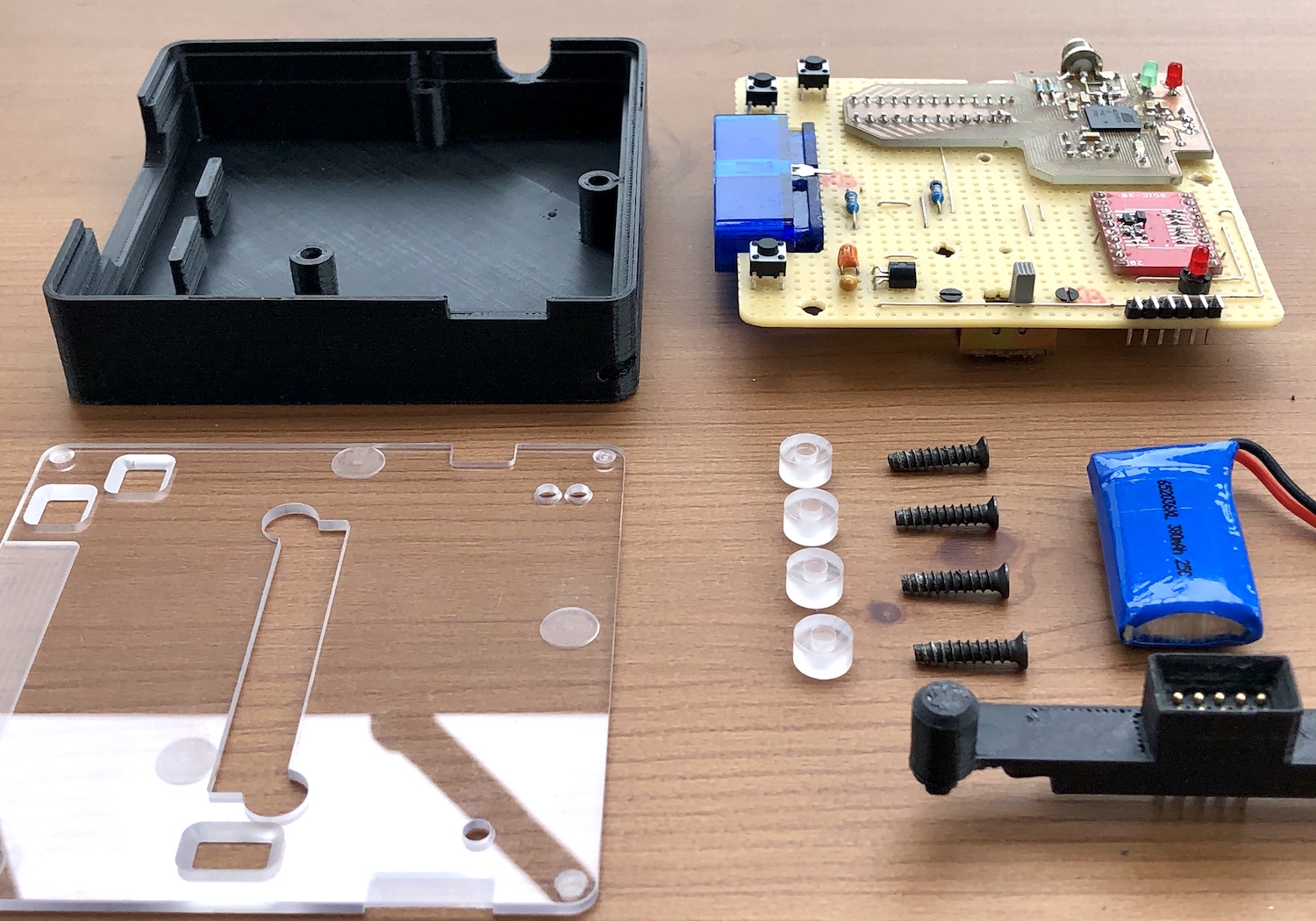
The base station follows the same principles, materials and manufacturing techniques.
When practicing flying, especially indoors with an unfinished project, it made sense to make bumper guards for the propellers to keep the propeller costs somewhat low.
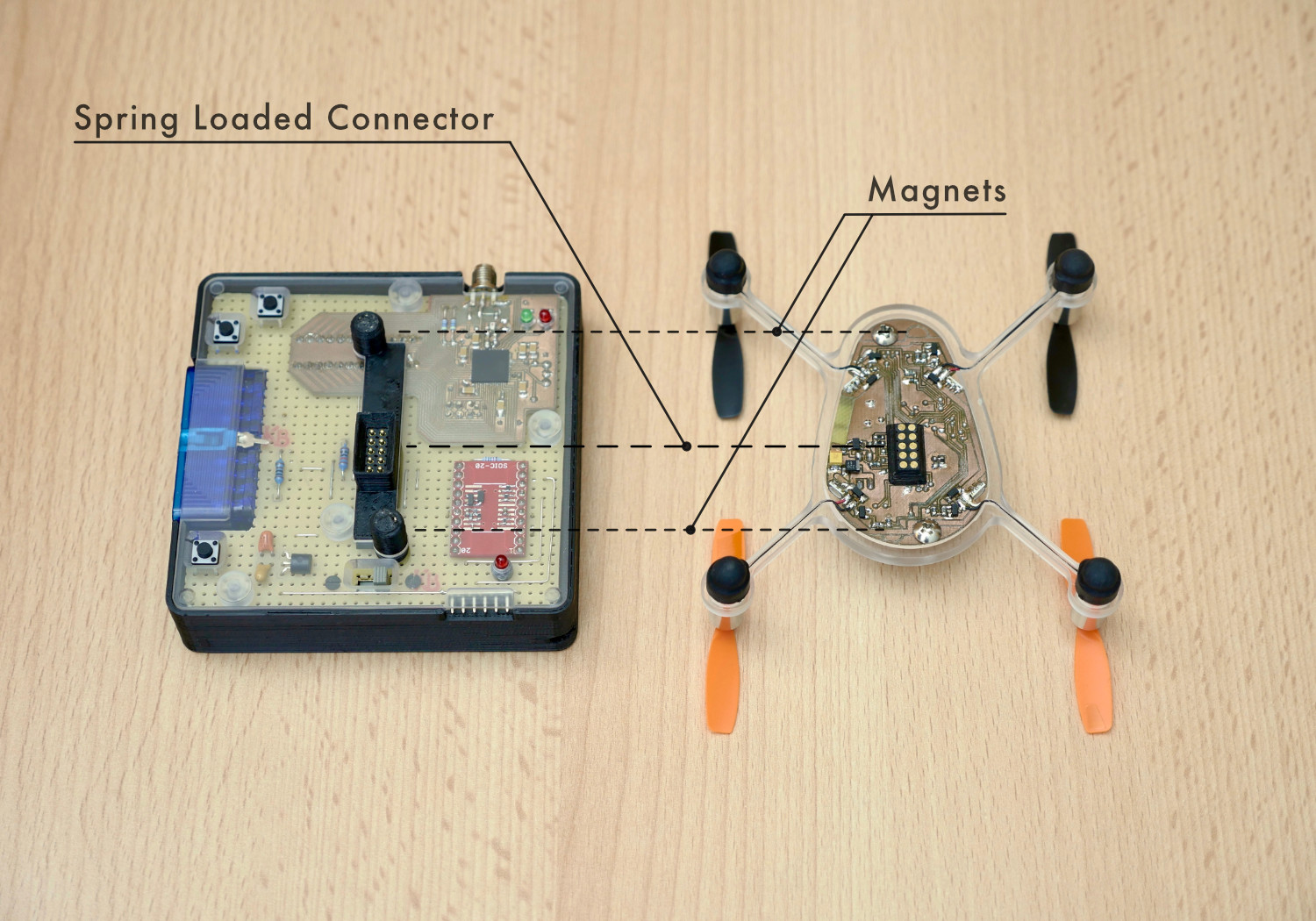
Magnets seemed to be a nice solution for things that are regularly taken apart. The Picopter has two strong 2x5mm magnets in the front and the back. A magnetic battery holder holds the battery on top. And on the bottom side the copter can be magnetically attached to the base station. A pin header sticking out on the side of the copter would not go well with what I had envisioned. So I tried to use spring-loaded connectors. The copter has flat golden target contacts on the bottom and the base station has spring loaded piston contacts. Both sides have 3D-printed bevelled parts to guide them to the correct position. And again the magnets pull them together. The spring-loaded pistons had to be placed at the optimum height in relation to the magnets, too high, and the magnets would be too far apart, too low, and some contacts might lose contact. I am very happy that this solution worked in the end.
All this needed several iterations to get to the point where I was satisfied. Over the years I used SolidWorks, FreeCAD and TopSolid to design the various 3D models. The parts were milled on Datron machines or printed in 3D on my Thing-O-Matic 3D printer.
Electronics
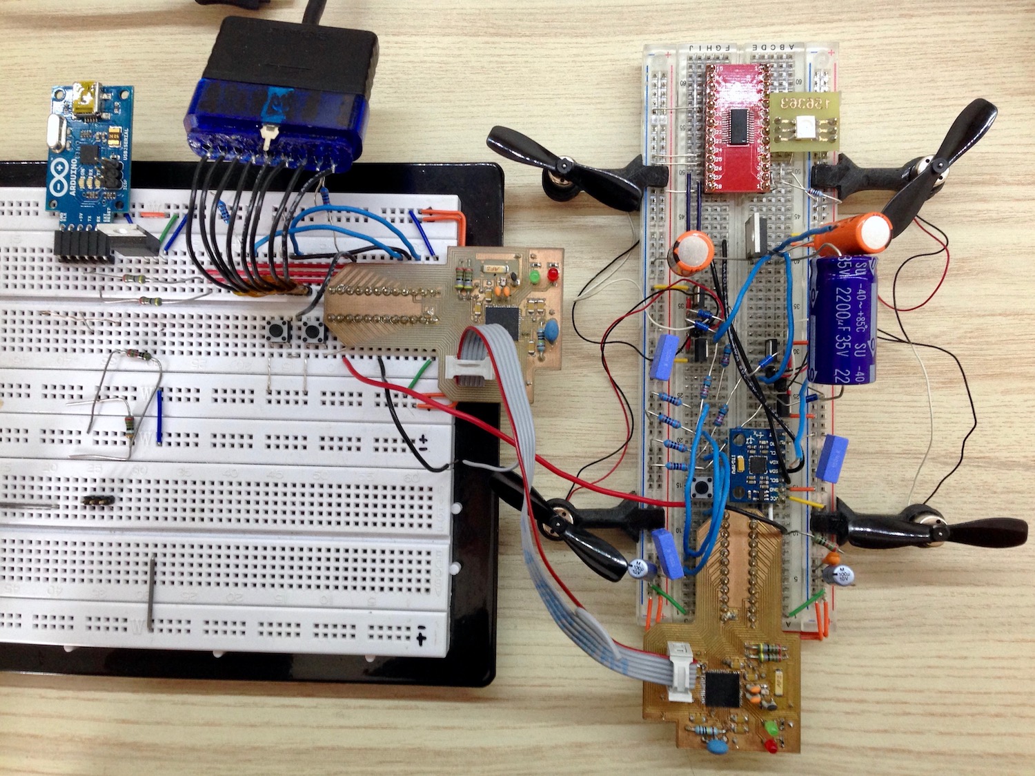
First I wanted to know if I could get the electronics and software to work at all. So before I designed and built the real thing, I decided to collect some experiences with a development board. Because the copter and the base station use the same microcontroller ATmega128RFA1, I made two of the development boards, so I could also test the communication. The package of the microcontroller and also the IMU are designed for reflow soldering (using solder paste and a reflow oven with a certain temperature profile). But I saw somewhere in the Internez that someone soldered these packages with a heat gun, and since I like to experiment, I tried that for myself… let's say it worked in the end, but I wouldn't recommend it to anyone. Don't get too close or you'll fry the microcontroller or just blow it away, it was nerve-wracking.
Having the development boards ready I set the microcontroller fuses and burned a bootloader on the base station dev board with an additional Arduino UNO as ISP and some flat cables. With the bootloader and a little USB to Serial board I was able to program the base station. The base station can also be temporarily converted into a programmer for the copter, which is really neat and this way I can also program the copter.
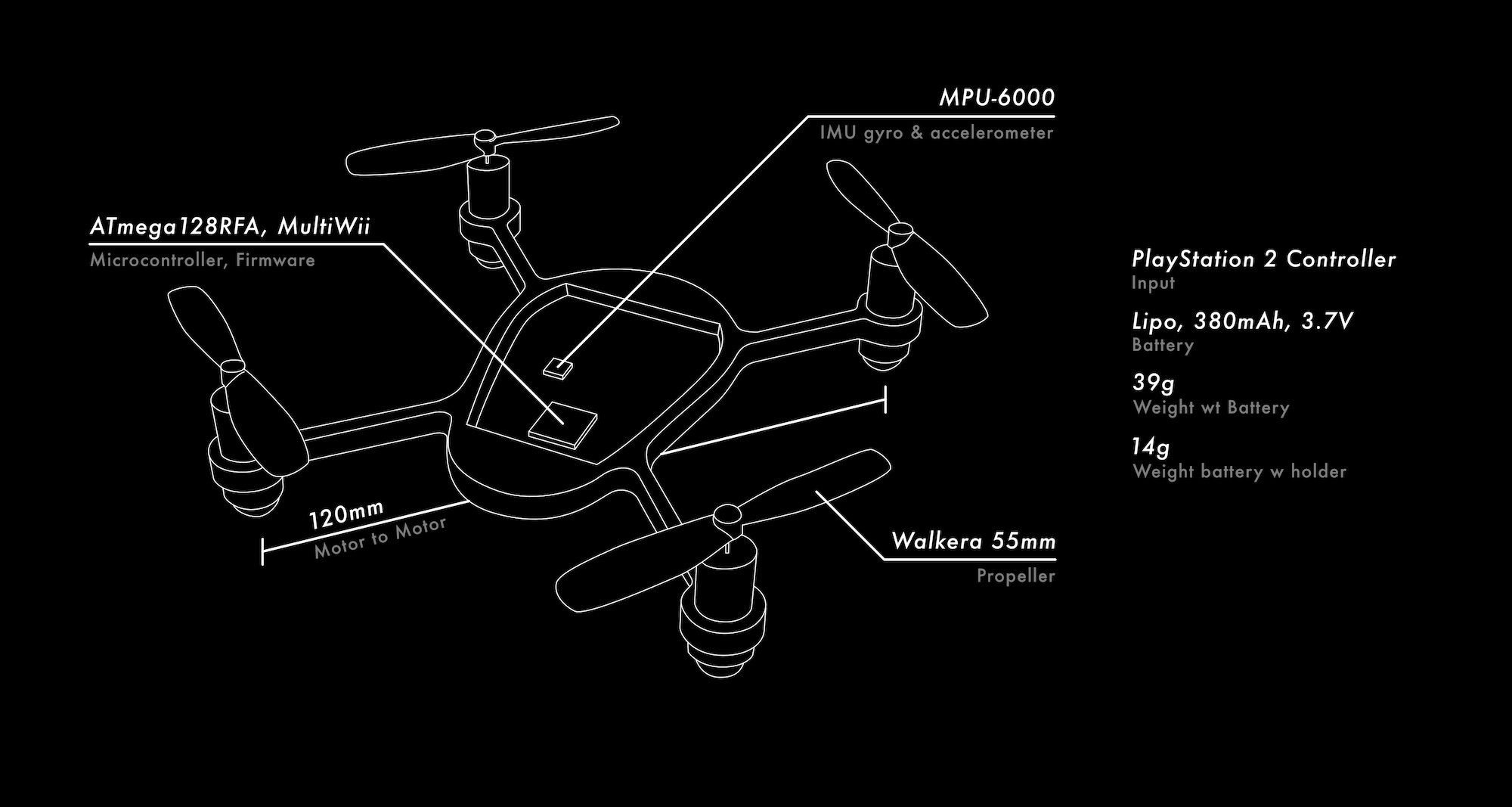
On two breadboards I finally built the circuit for the station and the copter. After testing the basic functionality, I was ready to add and test my ideas. Apart from the different shape and layout of the board, I wanted to add LEDs, which made an LED driver on the copter necessary, spring loaded connectors between base station and copter and instead of a Wii controller I wanted to use a PlayStation 2 controller. The idea was to have an RGB LED pointing into each of the transparent arms of the copter. This means that the LED driver has to be able to control 12 individual LEDs. The LED driver (PCA9952TW) uses I2C, which made it easier on the software side as it is also used to communicate with the IMU. To connect the PlayStation controller, I bought a cheap Dual port PS2 to USB Adapter and took it apart to get to the PS2 female connector.
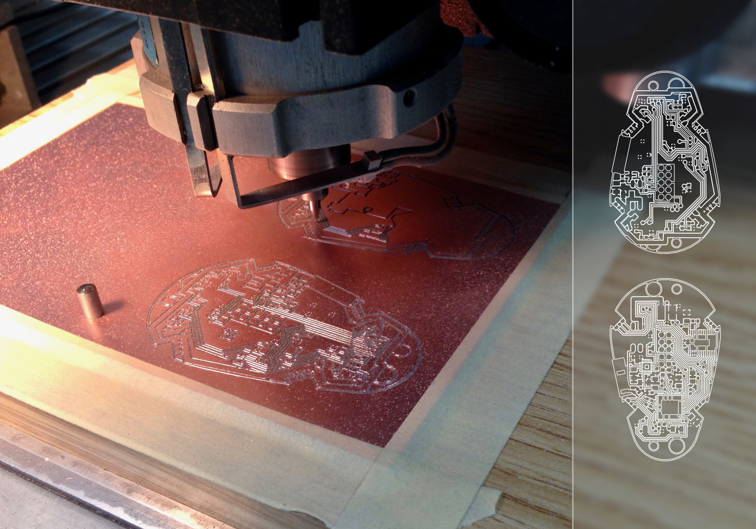
In Eagle I added the new parts to the circuit, completely rewired it and adapted the layout to the new shape. I found an Eagle script mill-outlines that allowed me to export the outlines of the traces as vector paths and that made it possible to mill the circuit board on a milling machine with a graver.
The base station has a built-in battery so that it can be used on the go. You can also connect the small USB-to-serial adapter, which also supplies 5V. So of course I added a charging controller to charge this battery with the USB power supply. But this led me again to the question how to handle multiple power supplies that are connected to a single circuit at the same time. This paper describes how to use an external power supply to charge a battery and power a circuit that is otherwise powered by that battery. The important component here is a P-channel MOSFET, which connects the battery to the circuit only when the USB power supply is absent. This is really handy, and the circuit can now immediately switch between the two power supplies.
Software
This project uses MultiWii as flight controller firmware. Originally developed to use Wii controllers as input devices, the firmware has evolved over time into a more universal firmware and according to them “truly father of many firmwares like CleanFlight, BetaFlight, iNav and others” [paraphrasing]. The original Picopter project is based on an outdated MultiWii codebase. I thought it would be a good idea to use the latest code with more features and bug fixes. So I tried to identify the changes made by the original Picotper project and introduced them into the current and actually quite different version of the firmware. One of the main changes is that a library called PicopterRadio is used for radio communication, which in turn is based on the zigduino-radio library.
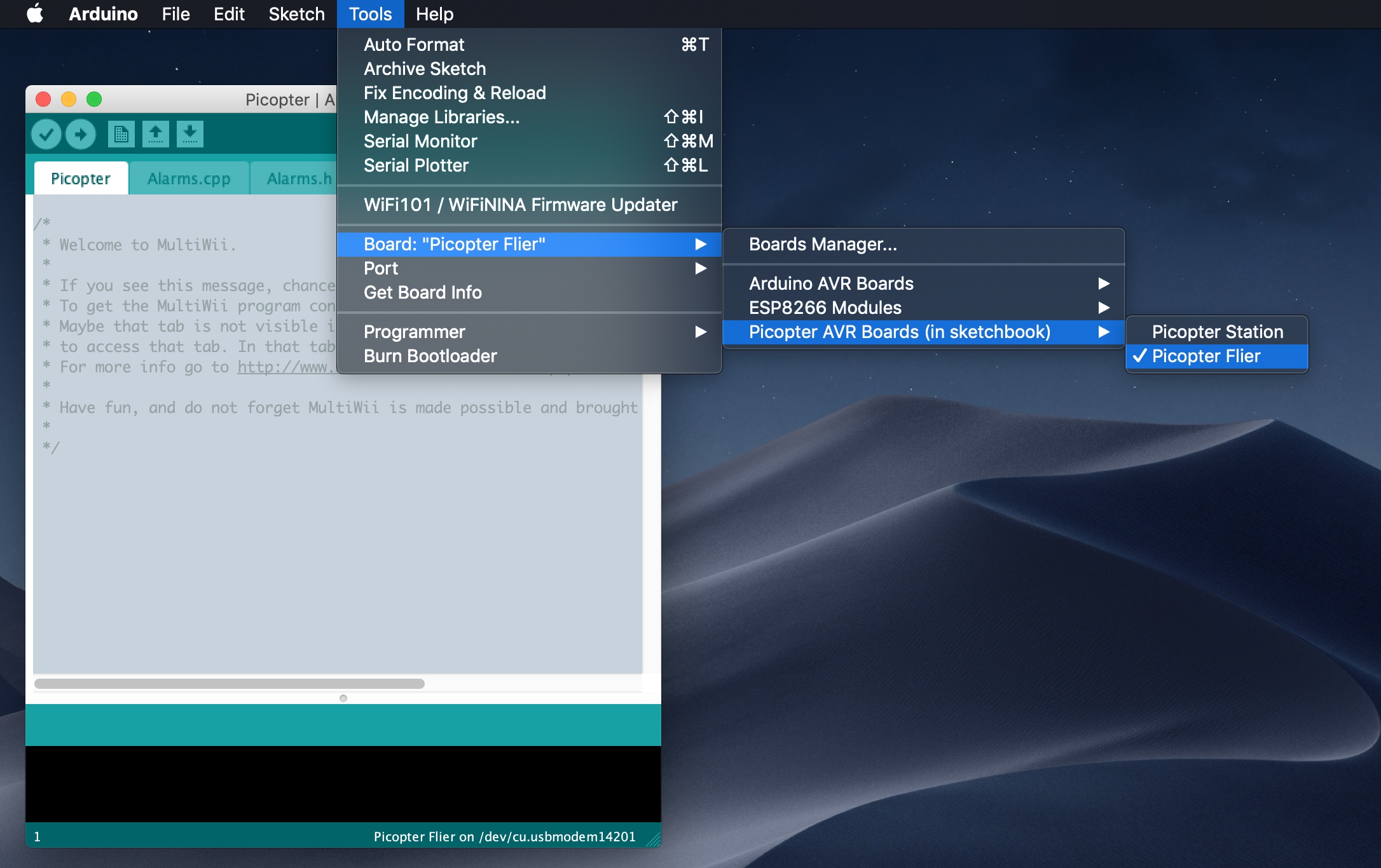
While I was modernizing the code, I also wanted to make sure it worked with current Arduino IDE versions. Originally it was based on Arduino 0023, which doesn't even run on current macOS versions anymore. For some time now, Arduino has been using a “sketchbook folder” where users can install additional libraries, but also add definitions of new hardware. This makes it possible to program other microcontrollers using the Arduino IDE. So I created a nice “hardware” package by updating the piocter_core so that it can be compiled with the new Arduino version. I also wrote a boards.txt which defines the station and copter boards and contains compile and upload instructions for the ATmega128RFA1. But there are two more things to improve here. First, I could not program the copter directly from the Arduino IDE and got the error message avrdude: verification error, first mismatch at byte 0x0002. To fix this, I had to add the -e (Perform a chip erase) option to the avrdude command, so at first I copied the command from the Arduino console and executed it with the -e in the terminal. Since this is cumbersome, I created my own platfrom.txt and added the option upload.extra_params to be able to set a flag for the upload command from the boards.txt.
platform.txt
tools.avrdude.upload.pattern="{cmd.path}" "-C{config.path}" {upload.verbose} {upload.verify} -p{build.mcu} -c{upload.protocol} "-P{serial.port}" -b{upload.speed} {upload.extra_params} -D "-Uflash:w:{build.path}/{build.project_name}.hex:i"
boards.txt
picopter_flier.name=Picopter Flier
[…]
picopter_flier.upload.extra_params=-e
Now I am able to select and use the copter and station with the same functionality as any other Arduino board within the Arduino IDE.
The other thing that could be improved was the definition of the pins of the microcontroller. For example, Arduino users are used to setting digital pin 13 to high digitalWrite(13, HIGH). But this number is not the actual name of the microcontroller's pin, there is a certain abstraction in the use of these pin numbers. The library Arduino-PS2X, which is used to read inputs from a PS2 controller, uses these Arduino pin definitions, but these have not yet been defined for the microcontroller used here. This can be fixed by creating a file called pins_arduino.h which is placed in hardware/picopter/avr/variants/picopter. pins_arduino.h basically contains a mapping between the microcontroller pins and some imaginary pin numbers, which could then be used e.g. for the Arduino-PS2X library.
The code running on the base station is called PicopterTransmitter. I modified it to get inputs from a PS2 controller using the Arduino-PS2X library. The range of the sticks was mapped to the requirements of the MultiWii firmware. The PicopterTransmitter code contains code similar to the ArduinoISP sketch to be able to use the base station as programmer for the copter. This programming mode is entered when no PS controller is connected or the cross button is pressed while booting the base station. To flash the base station, the bootloader must be activated by pressing another button on the base station while booting.
Code for the 4 RGB LEDs in the copter has also been added. The idea was to give clear and comprehensible feedback and maybe have a bit of fun. There is a default lighting, which can be interrupted by a notification. There are numerous notifications, e.g. change of flight mode or calibration of gyroscope or accelerometer. Each one with its own animation composed of pattern, color and timing. All this must be executed fast enough not to interfere with the main update loop.
Tuning and Improving
It was very difficult to fly the little copter. Without previous experience I thought it was a matter of practice and tuning the PID controllers. After much tuning and practice it was still super difficult to even hover. Also the radio range was noticeably bad... maybe the problem is related to the communication between transmitter and receiver? I fiddled around with the radio circuit of the base station and noticed by accident that if I connect one of the two balanced outputs of the microcontroller directly to the antenna and omit the balun, the signal strength increases significantly. This is in complete contrast to everything I have read and known about baluns, as this component is essential to match the 100Ω impedance of the microcontroller to the 50Ω impedance of the antenna and also converts the balanced signal to an unbalanced one. I'm not sure what's going on here, but for this project at this stage I'm satisfied with the result - if I were to fly as far away as the current signal strength allows, I wouldn't even see the orientation of the little copter.
The MultiWii Wiki has been offline for quite some time, but you can still browse it at Archive.org. This can be extremely helpful for some basic explanations, such as the different flight modes.
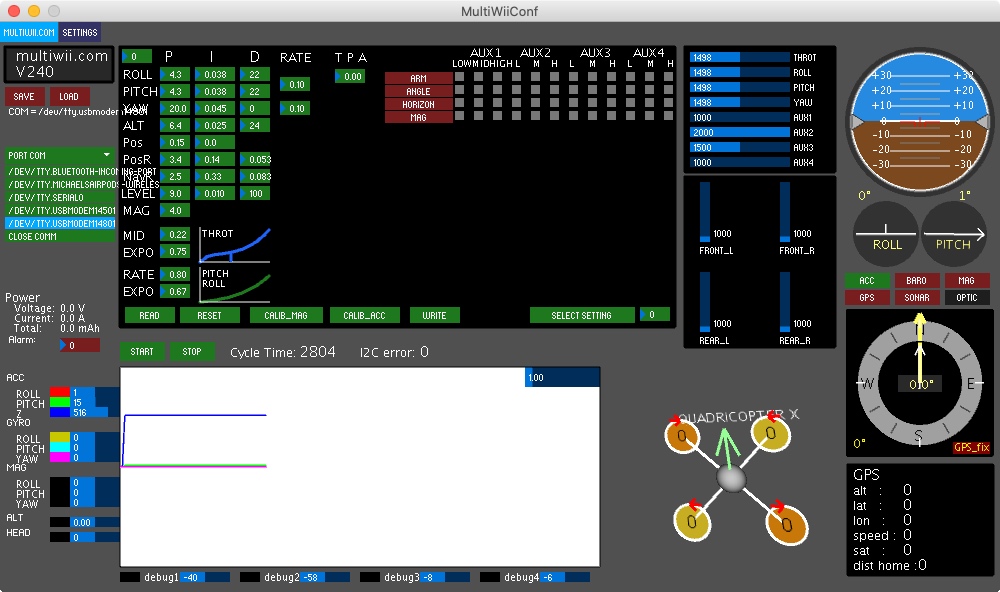
MultiWii comes with a Processing App “MultiWiiConf” that allows you to receive live data from the copter and set various values such as the PID controllers. Going into the P, I and D values is another rabbit hole that I will not go into here. There are two good Youtube videos that explain some basics quite well Video 1, Video 2. One thing I find noteworthy though is that low frequency oscillations are caused by an excess P-term which can be corrected by increasing D, while higher frequency oscillations are caused by an excess D-term which can be corrected by lowering it.
Another important thing is the proper functioning of the propellers. I have discarded the propeller recommendation from the original Picotper project and am now using 55 mm Walkera propellers, which are cheaper and have noticeably improved the lift of the copter. If you bump a propeller against something and it is only slightly damaged or bent, it can cause vibrations. So before PID tuning and generally before flying, make sure that the propellers do not swing up and oscillate. This can be easily checked by holding the copter and looking at the propellers from the side while applying some throttle. I have found two ways to repair propellers that are swinging up that are worth a try. First, make sure that both wings are at the same height, if not, bend the lower one a bit upwards – I think the propellers are a bit more stable if they are slightly bent upwards. If that doesn't help, the propeller might be unbalanced. You can balance it by putting it loosely on a wire, and if one side tends to sink down, apply a tiny piece of tape to the bottom side of the other wing.
Even with a better controllable and tuned copter I have to say that I still underestimated how much practice is needed to fly more dynamically, especially in confined indoor spaces and in orientations where the copter does not point straight away from you.
Potential for Improvement
- The battery voltage is directly connected to the motors, and they are then simply driven by N-channel MOSFETs. This is noticeable, because when the battery is discharging, its voltage drops as well, so I have to continuously adjust the throttle stick input to get the same throttle effect.
- The magnetic battery holder works great under “normal conditions”, but in crashes with higher impacts it may well come loose.
- At seemingly random times, the copter's microcontroller restarts or freezes. This is not exactly ideal and quite difficult to debug.
- The base station probably only transmits at half power, but as already mentioned, this does not really limit the flying fun of this copter.
Result
The default lighting is inspired by car lights, making it intuitively clear which side is front and which is back. While the copter is disarmed, the lights “breathe”, this picks up the organic concept of the hardware and gives feedback that the microcontroller is running. When the copter is armed, these lights stay on so that they are visible at all times. The default light can be interrupted by notifications. Everything related to the accelerometer uses green lights. Activation of the “angle mode” is confirmed by a green flash, while the progress of the accelerometer calibration is visualized by fading out green lights and trimming is indicated by green lights on the respective side. The “horizon mode” uses blue light - Horizon-Sky-Blue - to distinguish angle and horizon mode. The acrobatic mode, which uses only the gyroscope, is the default state, so white seems to be a good neutral choice for activating and calibrating the gyroscope. There are some more details, but most importantly there are two light effects on L2 and R2, completely for fun.
The stick controls are as you would expect from a quad copter remote, throttle and yaw on the left stick and pitch and roll on the right stick. Switching flight modes and the playful light effects are located on the shoulder buttons, which can be accessed while flying. The start and selection buttons are used for arming and disarming. By pressing the left stick (L3) the copter is also disarmed, so I can throttle and finally disarm with one hand and land the copter in the other hand. The D-pad buttons are used for trimming. The right stick button (R3) is used to program the EEPROM with the trim values. The square and triangle buttons are used to calibrate the accelerometer and gyroscope. Circle button to synchronize the radio channel between base station and copter. The cross button calibrates the controller sticks and sends some debugging messages to a connected computer.
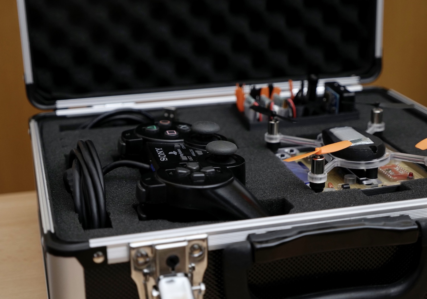
At this point, a tailored case seemed to be the perfect finishing touch for this project. It contains everything you need for flying, including spare parts. It also makes transportation very convenient. Inside is the picopter, which sits on the base station, the PS2 controller, a USB cable and a 3D printed box containing all the small parts like spare batteries, charger, spare propellers, the antenna and the USB-to-serial adapter. I can neither confirm nor deny that there are hidden compartments with additional spare parts.
PS: I started this project in 2013 and worked on it for about a year, but then life happened before the project was finished. Due to the 2020 circumstances I found some time to finally finish it. Things have moved on over the years, and if I would start this project today, I would do some things differently, for example I would use a more modern flight controller firmware.